A Takeaway From My First Radio Transmitter
By Martin Castillo on 2020-10-0866 Comments/Replies
"On Air"
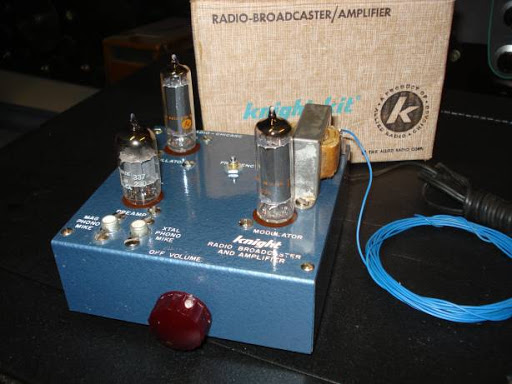
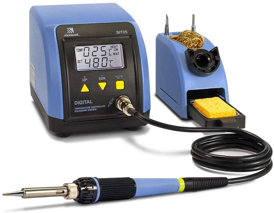
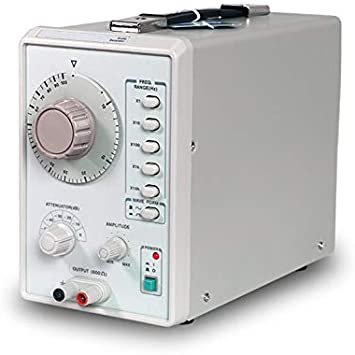
I still remember the day in May of 1966 in Davao City when I first went "On Air" with a radio transmitter that I built myself. It looked closely like the one in the picture above though much less polished. It was an optional project after the mandatory 5-tube AC-DC AM receiver to pass the course I was taking.
Encouraged by that initial success in receivers, I took on a challenge from my teacher in radio theory that I assemble a radio transmitter for the AM broadcast band, and in return, I'd get a 100 in his course. For me, the grade was just icing on the cake. Grade or no grade, I would still endeavor to assemble one just for the challenge itself.
A Diagram And Parts List
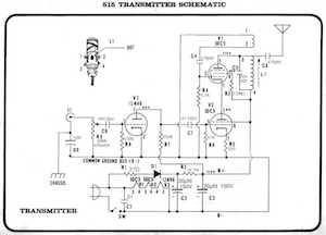
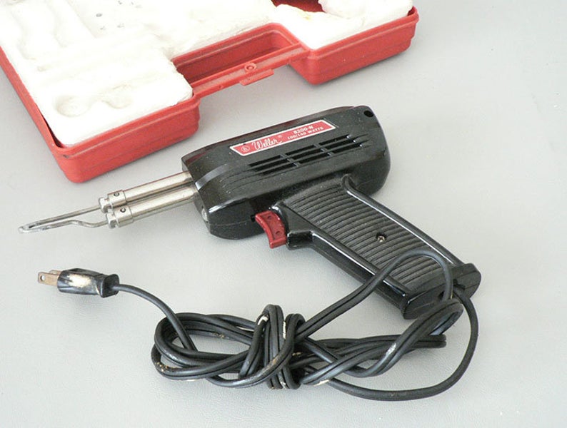
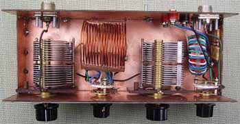
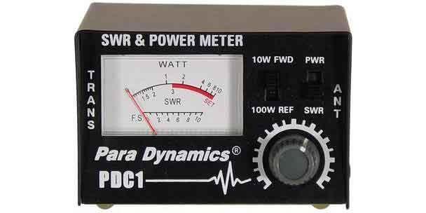
He provided the diagram which is very similar to the picture below. It came with a parts list. The total cost would be much less than 100 pesos, from a quick survey. This does not include the basic tools for radio assembly, like, soldering iron, multitester, long-nose pliers, etc.. Fortunately, I already had most of these on my workbench save for the electric drill and the chassis puncher which were available at school.
Theoretical Considerations
My inexperience in transmitter theory resulted in multiple chassis layouts that my teacher disapproved of due to violations in component placement theory and best practices.
He gave me a lecture on the importance of keeping the adjacent transformer cores at 90 degrees from each other and, keeping the low-signal tubes far from transformers and from high-signal wires to prevent unwanted feedback that could end in an interference, spurious oscillation, and radiation.
He added that the connecting wires must be kept very close to the chassis and be as short as possible just enough to make the connection and, to use shielded wires for audio signal-carrying connections. And several other tips that sounded greek to me at the time. Nonetheless, I would follow each one as accurately as I could. But, could I?
Theory Vs. Reality
We all know how theory and reality can quickly go incongruent and butt heads in almost every way when one wants to do stuff the perfect way. Suddenly the word "perfect" becomes an enemy you don't want to have to deal with, or, be friends with. This is where the word "compromise" becomes a friend and an attractive option. Like always.
The physical limitations of the small chassis added layers of compromises dragging my work even farther away from the theoretical prescriptions which I have now conveniently set sail for my own sanity. Bye-bye, "Perfect".
The Unpredictability Of Kit-Building
In any DIY project, anything unpredictable could happen. Just when you think that you have everything under your thumb after doing countless once-overs, something sneaks in and kills the excitement.
It could come in many forms.... from tubes not lighting up, fuse blowing for no apparent reason, overheating components, and, to a more literally explosive surprise, from an electrolytic capacitor, connected the wrong way. I've encountered those in my AC-DC radio project.
This project was no exception. While there were no fireworks, and the tubes all lit up, it would not transmit any signal, wherever I tuned the nearby receiver across the entire broadcast band from 540khz all the way to 1600khz. A deafening silence was all I got. A huge letdown.
Early Troubleshooting, Ouch!!
Being a neophyte in troubleshooting, I just did a random check on overheating resistors by carefully touching each suspect with a finger, (looking back now, that was plain stupid), checking solder connections for integrity by moving a wire back and forth, again, using my finger!
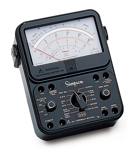
It was not long before my fingers wandered, and accidentally touched a terminal, that electrified me profoundly! The multitester read 250Volts DC!. Ouch!!
Maybe it was time to get some rest and be back at it another day. Or maybe, I missed something that I overlooked not doing. Or maybe something else, like, more info about the diagram and the expected voltages at the crucial points in it.
"So Near Yet So Far Away"
Back to my teacher, I asked for more information about the expected voltages at key points and their acceptable deviations. It took me sometime reconciling the key points in the diagram with their actual locations under the chassis.
For what would appear to be two points right next to each other as drawn in the diagram, could actually be at opposite ends under the chassis, physically far from each other.
Or the reverse could be true. Two components that are mounted physically close to each other, could be drawn so far away from each other in the diagram. It reminds me of the song, "So Near, Yet So Far Away".
Information Is Key
With the electrical information on hand, I soon discovered the offending connection, where an expected voltage of 85V to 95V, only 10V reached it. Why? How? What to do next?
I did not realize that at that moment, I was thinking like an engineer, analyzing causes and effects, considering possible options to do next, and eventually figuring out probable solutions based on whatever findings I might get my hands on.
Carefully, I traced the connecting wire from the offending point to the power supply itself. One resistor stood between that point and the power supply. One end of the resistor connected to the power supply had 140V, which was expected at that point, and the other end leading to the offending point was only 10V. Too low from the expected 90V.
Color Me Blind
Only two things could be the reason for it. Either the resistor was defective or I put in a wrong resistor. A quick check with the diagram revealed that it should be a 1 KOhms or 1000 ohms. Its color band must be Brown Black Red. The resistor installed had a color band of Brown Black Orange which means it's a 10KiloOhm or ten thousand Ohms resistor. Ten times electrically bigger.
No wonder it dropped the voltage too low to be usable. I mistook the Red for the Orange band. Perhaps the guy at the store was colorblind himself and gave me the wrong one. Ransacking my bins for old resistors, I found three 1000 ohm ones which tested good.
Hallelujah! The Moment Of Truth
Installed the resistor, turned on the switch, and waited for the 11-second countdown as the tubes warmed up. And.... Voila!!! The little bulb, used as a dummy load in lieu of an antenna, began to glow dimly at first and increasingly glowed brighter and brighter, signifying it was getting power from the transmitter.
I was in utter disbelief. It was so unreal to be true!! Like a dream! I sat for an eternity staring at the project in amazement, disbelief and silent celebration, as I let the reality sink in. Even today, as I was writing this, I relived that moment of triumph that only I could completely understand, appreciate and feast on. Easily one of my life's priceless memories.
Christmas In May
But, can it actually cause music to be heard through my radio? By touching the input terminal, I should hear a humming sound from the radio tuned to the frequency set for my transmitter. And I did!!! Plugged my turntable and played a long play 33RPM Christmas album by the Ray Conniff Singers, my all-time favorite. I played both sides, repeatedly. Never mind if it was May. To me, that was definitely, Christmas in May.

My Take Away
This blog has gone longer than I had wanted it to be.
So let me end, by underscoring the impact that project building has had on me growing up, and, that even today, I still hold dear the catalystic influence it has on me to do something new and different, and to remain unfazed against the difficulties that come with any undertaking.
Indeed, that transmitter has a special place in my wealth of memories. And. why not? It was from my encounter with it that I picked up an important takeaway that does not fail to remind me that...
Most often than not, what appears to be a mountain of a rock to climb could actually be just a small pebble, but is only falsely magnified by our own ignorance and lack of understanding of it, coupled with our unwillingness to uncover its true nature.
Thank you, for taking the time to read.
Stay safe.
Martin Castillo is a long-time electronics enthusiast, experimenter and, hobbyist. He is currently based in Houston.